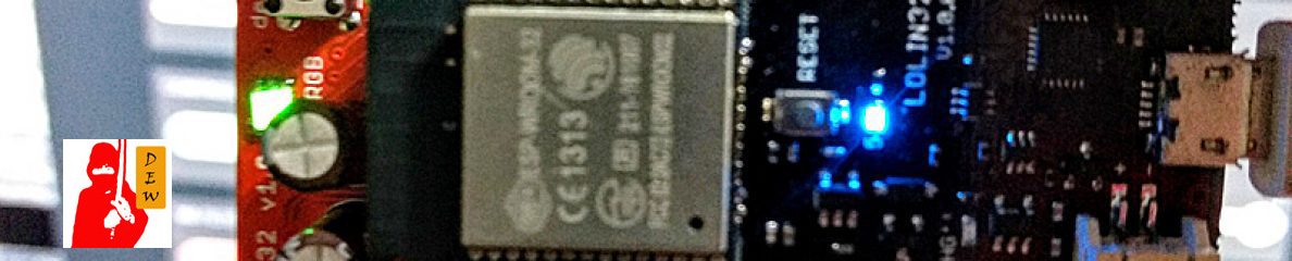

In this article, we examine an I2C module provided in the PIC24EP family. The same PIC24EP256MC202 prototype board is used. We start from a simple hardware setup. An MCP4725, 12-bit DAC, from Microchip is used as slave device. The chip is soldered to the prototype as shown in the figure above. (Well, if you are in a country where an inexpensive breakout board is available, I recommend you buy one. Soldering work is cumbersome with this tiny IC.)
Hardware Setup
SCL and SDA pins of the two ICs are wired together. Note that the PIC24EP256MC202 has ASDL1 and ASDA1 for I2C1 module, where A stands for “Alternate.” Surprisingly enough, I could not find a primary SDL1 and SDA1 from the datasheet. Standard I2C requires that the two wires must be pulled up by resistors with value range between 1K to 10K ohms. Here we use a pair of 2.2K ohms from my component stock. The MCP4725 has only 6 pins. The SCL and SDA are taken care of. Vdd and Vss are connected to 3.3 V and GND, respectively. (The datasheet recommends putting a 0.1 mF bypass capacitor close to the supply pin.) Pin 1 is the DAC output. So what’s left is pin 6 (A0). This is your selectable DAC address. It means you can have two ICs on the same I2C bus differentiated by this address pin. Here I connect it to GND for value 0.
Figure 1 I2C connection between PIC24E and MCP4725 Note: From Microchip datasheet, if a customer wishes to have more than two MCP4725s on the same bus, he/she can have internal address A2 and A1 customized in the ordering process. The factory default is 00.
Configure the PIC24E I2C Pins
Before we go into the C code detail, one issue that is worth mentioning is on the use of alternate I2C pins ASCL1 and ASDA1. As mentioned before, even though I could not find primary pins for the I2C, I still have to tell the PIC to use alternate pins. To do so, this configuration command must be put at the top of source file._FPOR(ALTI2C1_ON);Don’t forget this. It did take me hours to figure out why the I2C module didn’t function. Also, make the ASCL1 and ASDA1 open-drain
 ODCBbits.ODCB8=0;  // ASCL1
 ODCBbits.ODCB9=0;  // ASDA1
